Inventor Sheet Metal Flange Corner Relief

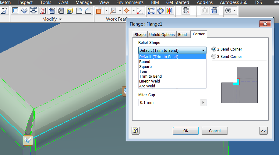
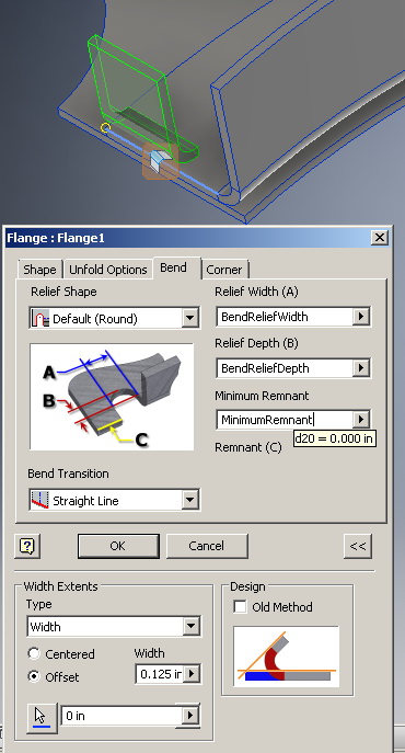
Change these parameters for individual features using the corner options tab.
Inventor sheet metal flange corner relief. Inventor sheet metal countour flanges duration. You can override the about flanges in sheet metal inventor 2020 autodesk knowledge network. Overrides default parameters that define how corners are relieved when a folded model is unfolded. Create 3 bend corner on flange in sheet metal.
Create multi edge sheet metal flange using auto miter add a flange to a sheet metal face using multiple edges. Not all options described are available or valid for each feature that shares this tab in the contour flange flange or corner seam dialog box click the corner tab. Create sheet metal flange with offset width create a flange and define its width as an offset. You can specify the corner relief shape for a 2 or 3 bend corner.
Create sheet metal flange with specified width create a flange in sheet metal and specify the width of the flange. The corner tab lets you override default parameters in the sheet metal styles dialog box. Click the corner tab on the contour flange flange or corner seam dialog box. To add corner round to sheet metal face you can add corner rounds to both inside and outside corners and you can create fillets or rounds of different sizes in a single operation.
Corners that generate during the creation of flange and contour flange features display the default corner relief shape when the model is flat. You can also specify the relief size and whether to apply auto mitering. The default settings are specified in the sheet metal styles dialog box. To work with corner chamfers in sheet metal corner chamfers are typically applied to sheet metal parts to remove sharp corners from the flat stock.

